28 Apr Auto-to-Manual Part 2
Auto-to-manual conversion: the how-to continues.
By Brian Gillespie
Our project car is a 2004 RSX base model and that effects the wiring when going from auto-to-manual. The following modifications work on the 2001 to 2004 models of RSX. If you have an 05 or 06, there will be some differences. I strongly suggest getting a Helm service manual or electrical troubleshooting manual to help with wiring if you have the later model. The manuals are available at helminc.com.
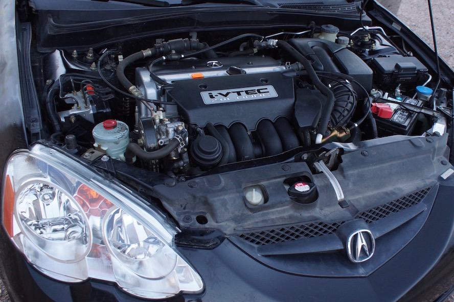
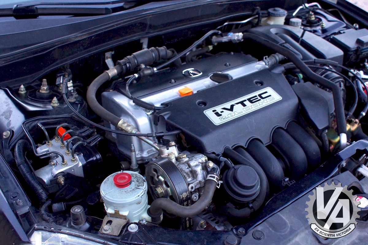
To first thing we did to prep for the new transmission was drop the engine and transmission. This isn’t strictly necessary, but it made it easier to remove, modify and reinstall the engine harness, not to mention the new transmission. Once again, I suggest getting an RSX service manual from Helm Inc. to help with the removal of the engine. You can buy the manual on line from helminc.com or if you have a PC with Windows Internet Explorer, you can access the information in PDF format online from Honda at Service Express for a small fee. You’ll only get one day of access for your $10 or $20 payment, but you can print the PDFs if you’re a slow worker.
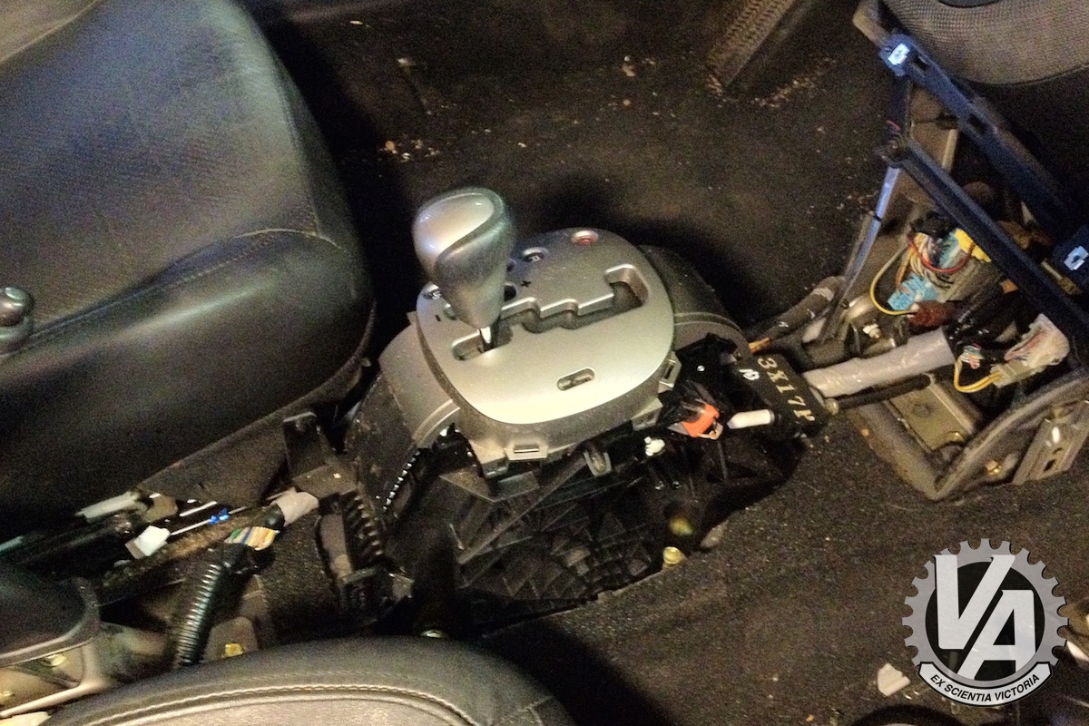
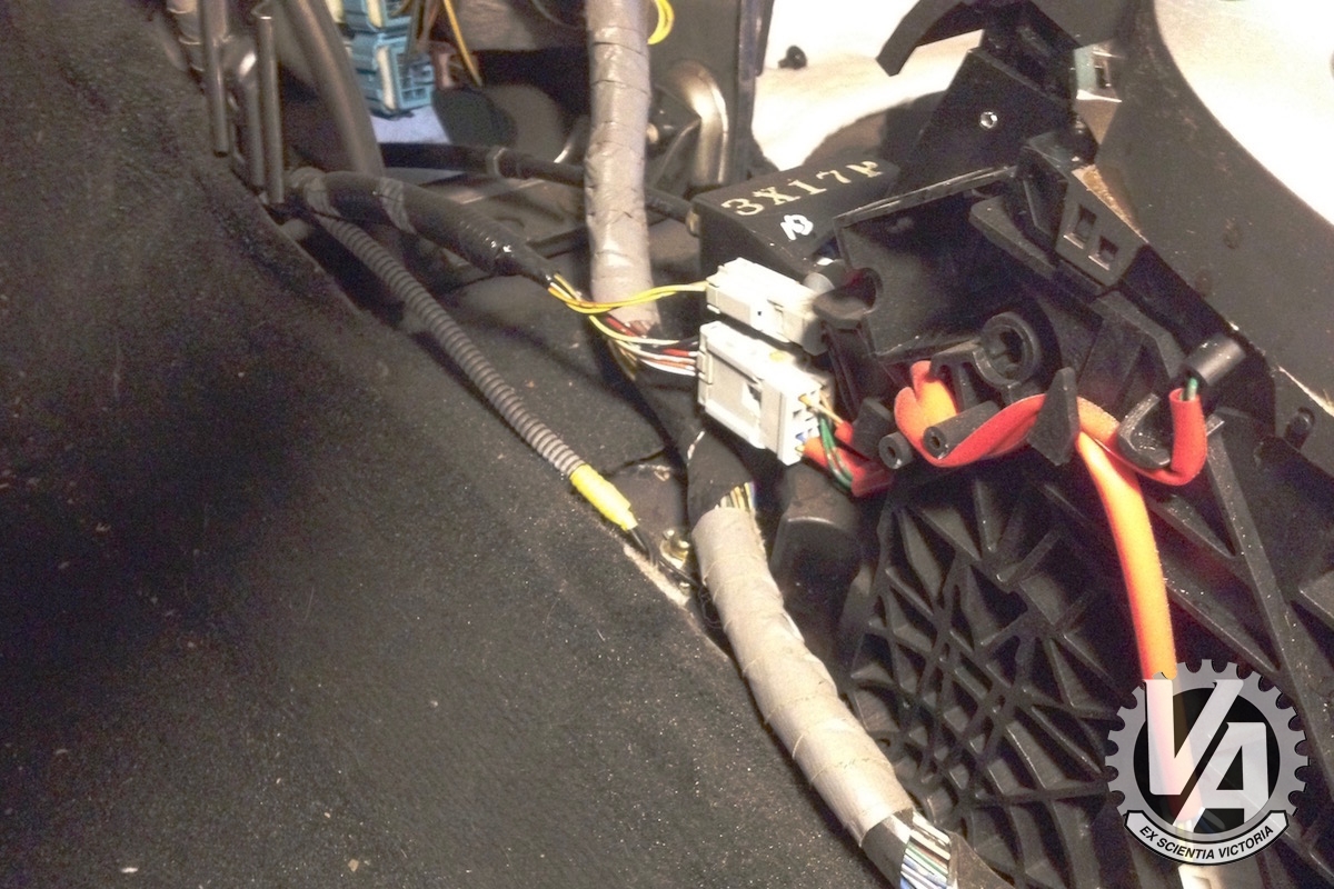
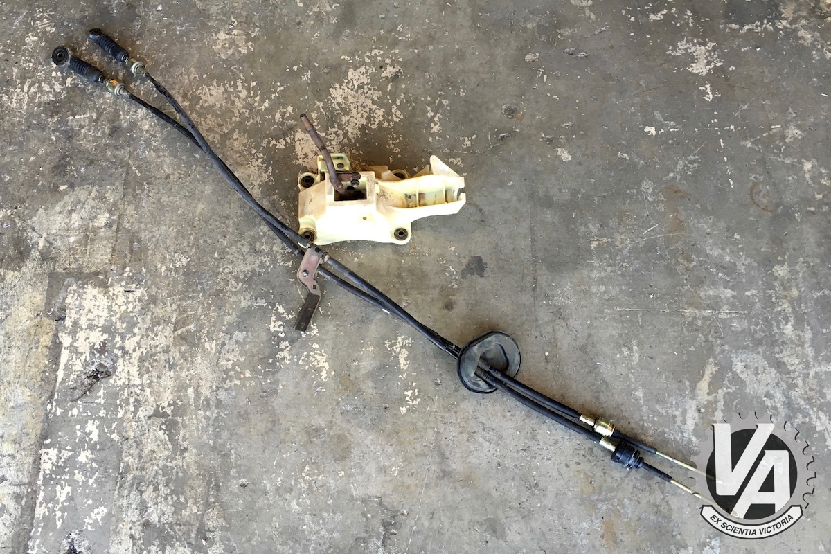
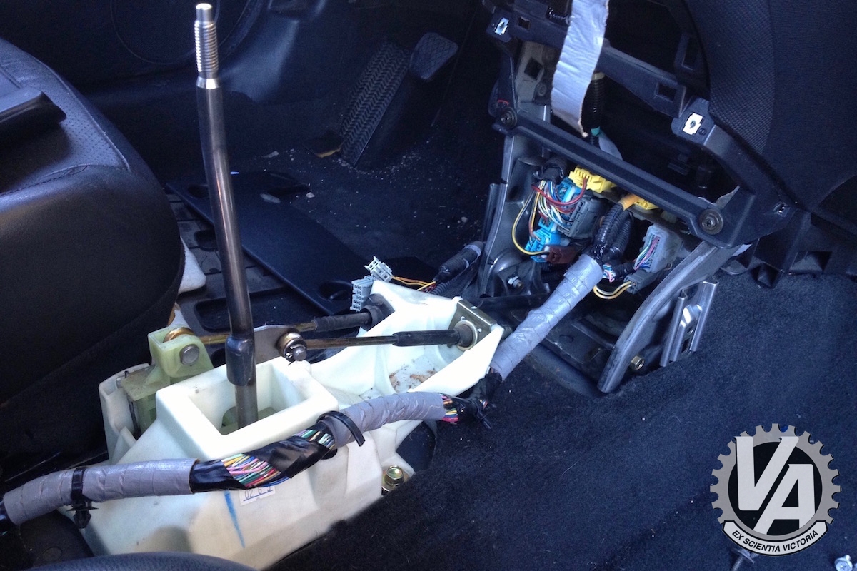
Next up was the shift mechanism. The stock automatic shifter is a huge heavy thing and has some electrical connections for the AT Interlock System. That keeps you from removing the key if the car isn’t in park. These don’t really pose a big problem. Once the shifter is unplugged and removed removed the interlock stops working. Problem solved.
Installing the new shifter is as simple as bolting it in using slightly longer bolts and the same mount holes as the A/T shifter. The shifter can come from a 5-speed or 6-speed RSX. Mine actually came from a 2001 Civic DX, it’s very similar and about $40 cheaper. The shift cables though have to be for a 5- or 6-speed RSX. Conveniently, the shift cables and grommet seals fit through the same opening as the A/T shift cable.
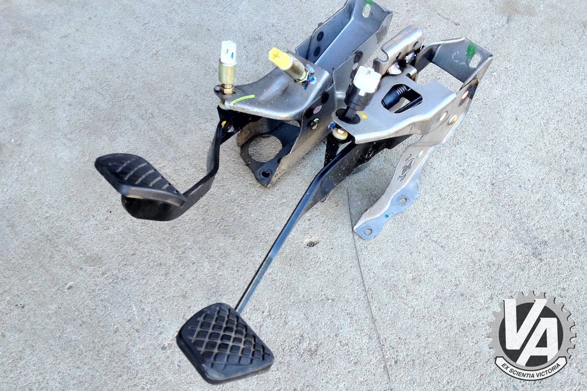
We’ll need a new brake and clutch pedal for our car. You can source them from an RSX or from the 02-05 Civic Si. RC at RC’s Garage happened to be doing a RHD drive conversion in an EP3 and had an extra set of pedals from the JDM Type R. I was able to score the pedals and the clutch master cylinder. The lines for left-hand drive are different so I bought those new. If not for the car at RC’s I would have found an RSX donor car. If you do, I suggest getting both pedals, the clutch master cylinder and any and all clutch lines and brackets.
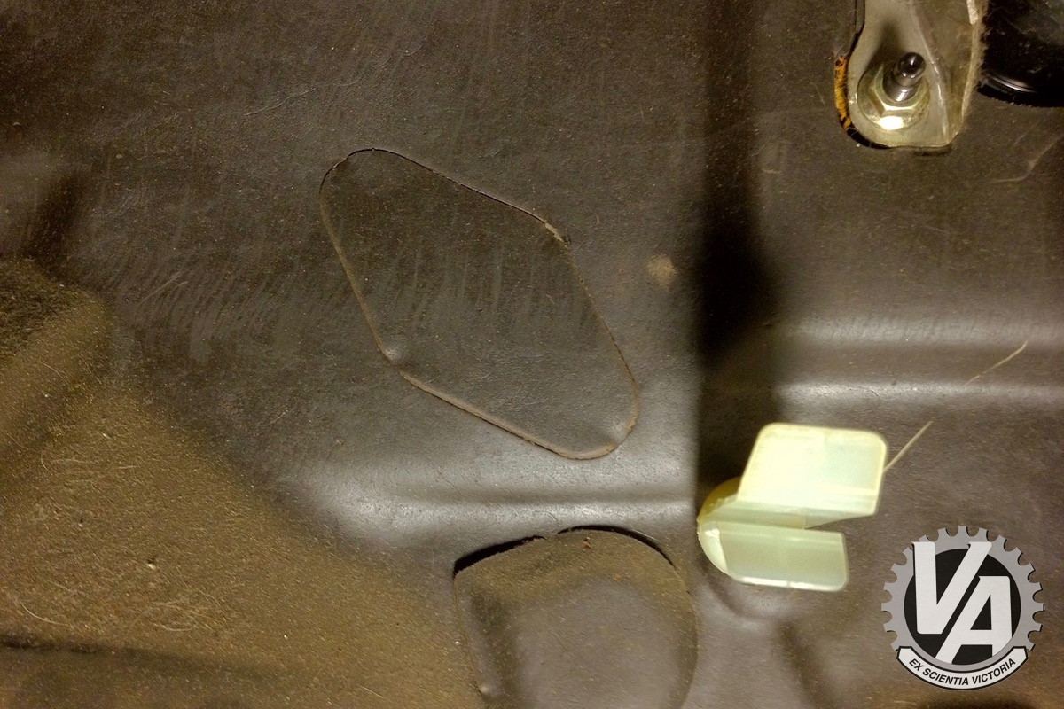
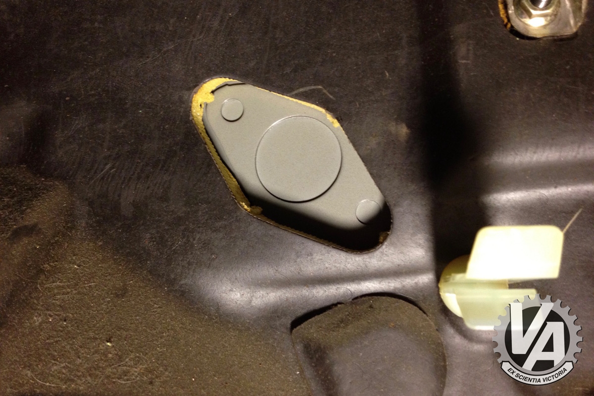
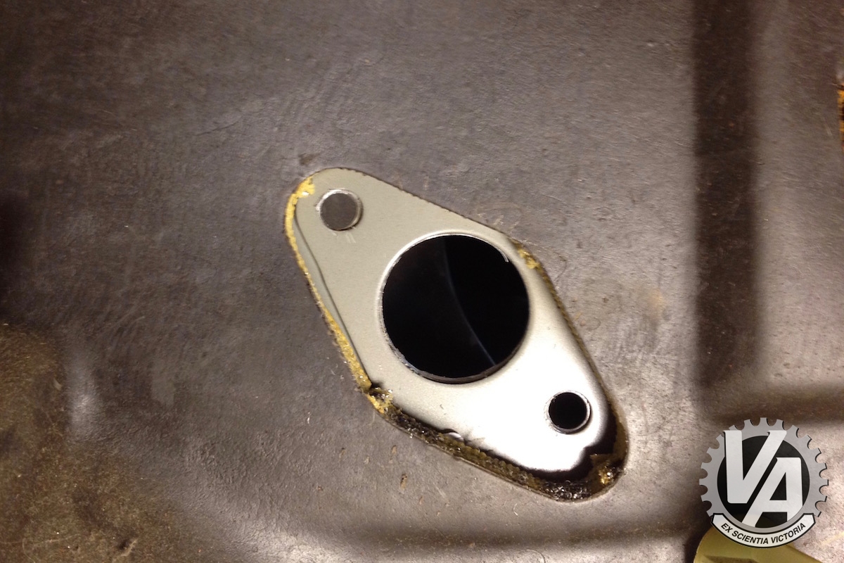
Unlike Civics and Integras from earlier models there are no holes in the firewall for mounting the clutch pedal. Upon inspection of the firewall you can see where the pedals would mount though. This may not be so hard after all.
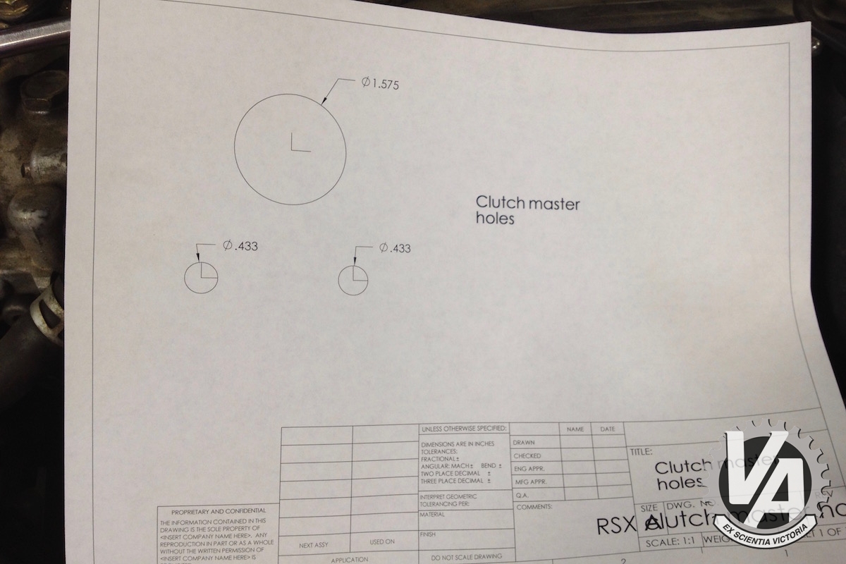
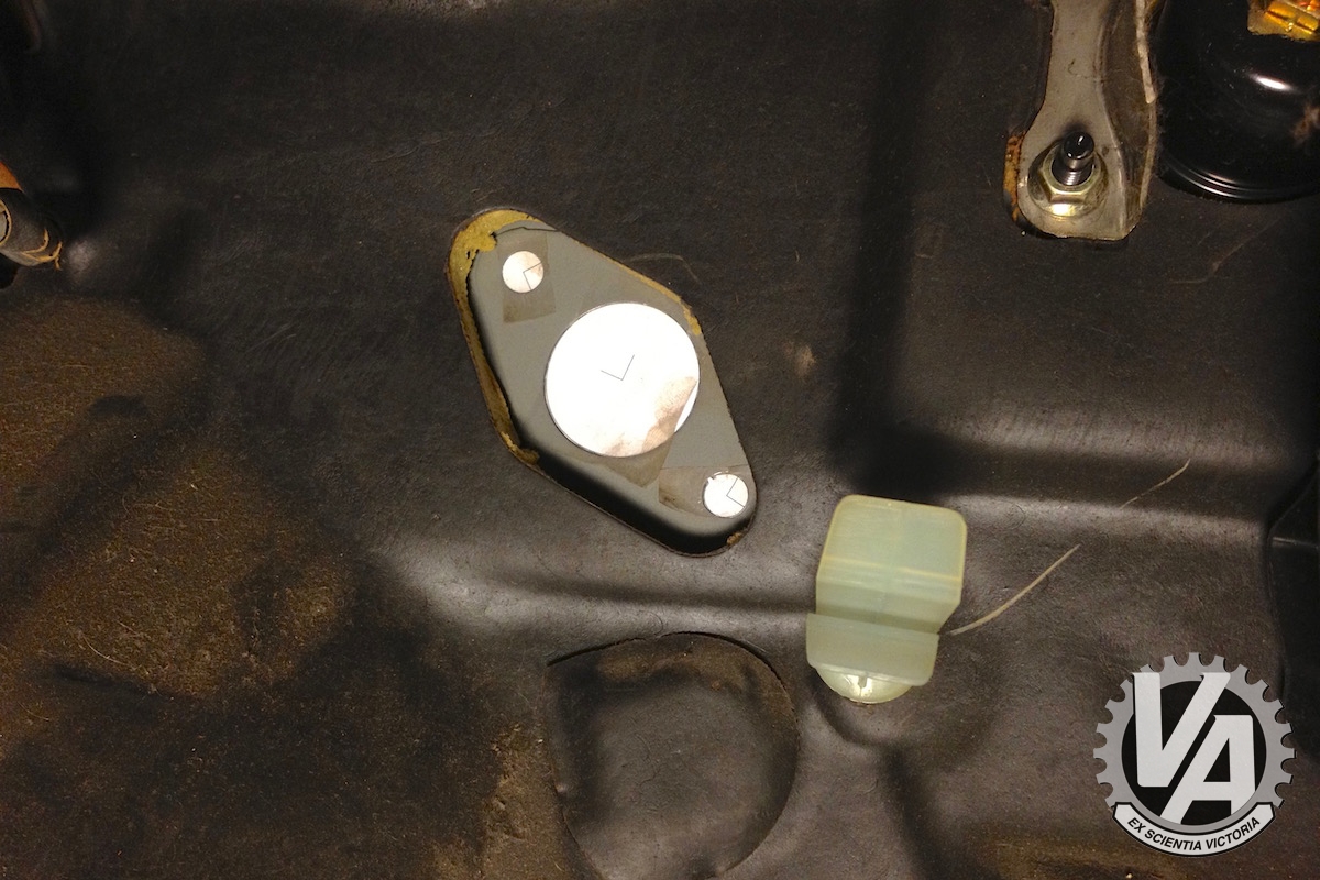
I got all anal and made some paper patterns of the holes so I could make sure I marked the center point and drilled accurately.
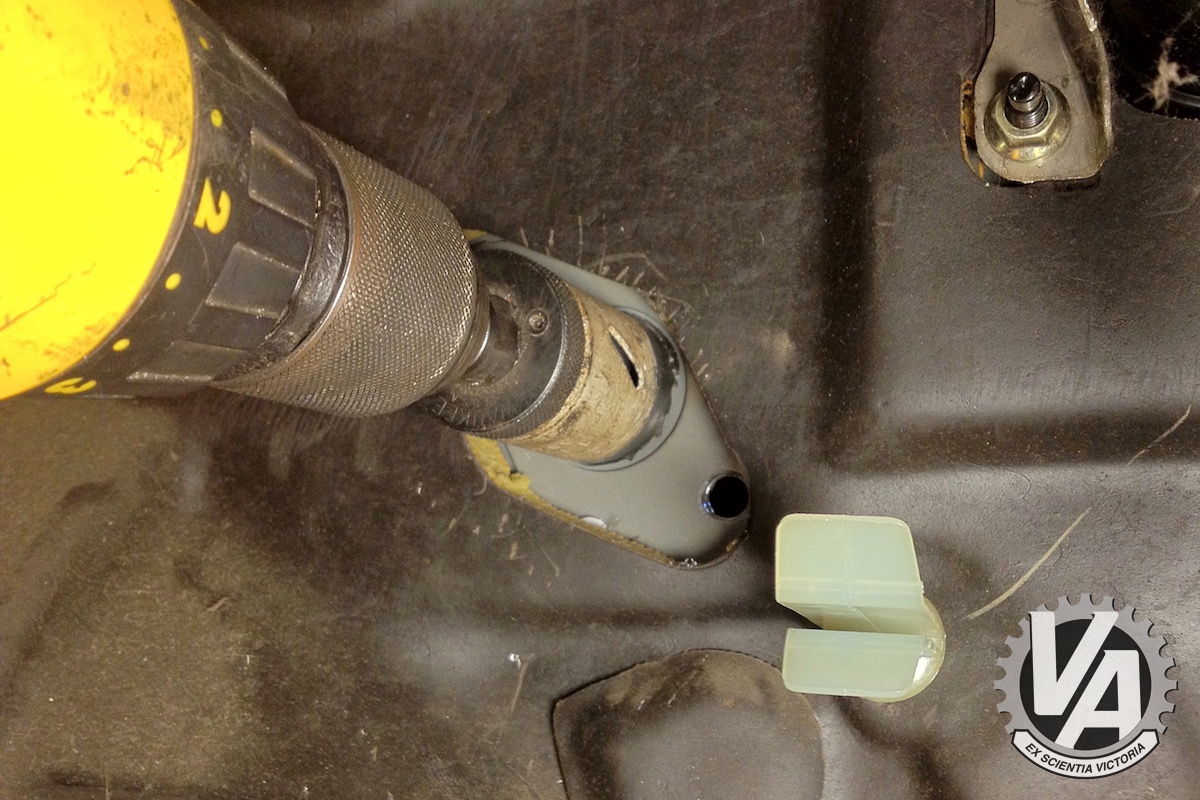
Once the holes center were determined I used a 7/16″ drill bit and 1 1/2″ hole saw to make the holes.
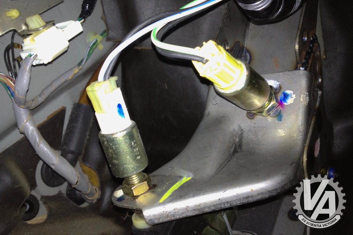
With the clutch and brake pedals installed there were some new electrical connectors to hook up. The new brake pedal’s switch was the same as the old one, but now there were two new connections for the clutch pedal. The top switch is for the starter interlock so you can’t start the car while it’s in gear unless the clutch is depressed. The one on bottom is for the clutch position. It turns the cruise control off if you hit the clutch. You don’t have to have these switches, but unless you are building a race car, I’d hook them up.
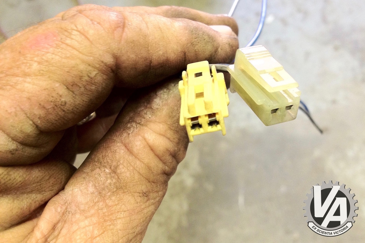
I harvested some connectors for the clutch switches from a salvage yard. You can find them on Accords and Civics that are 5-20 years old.
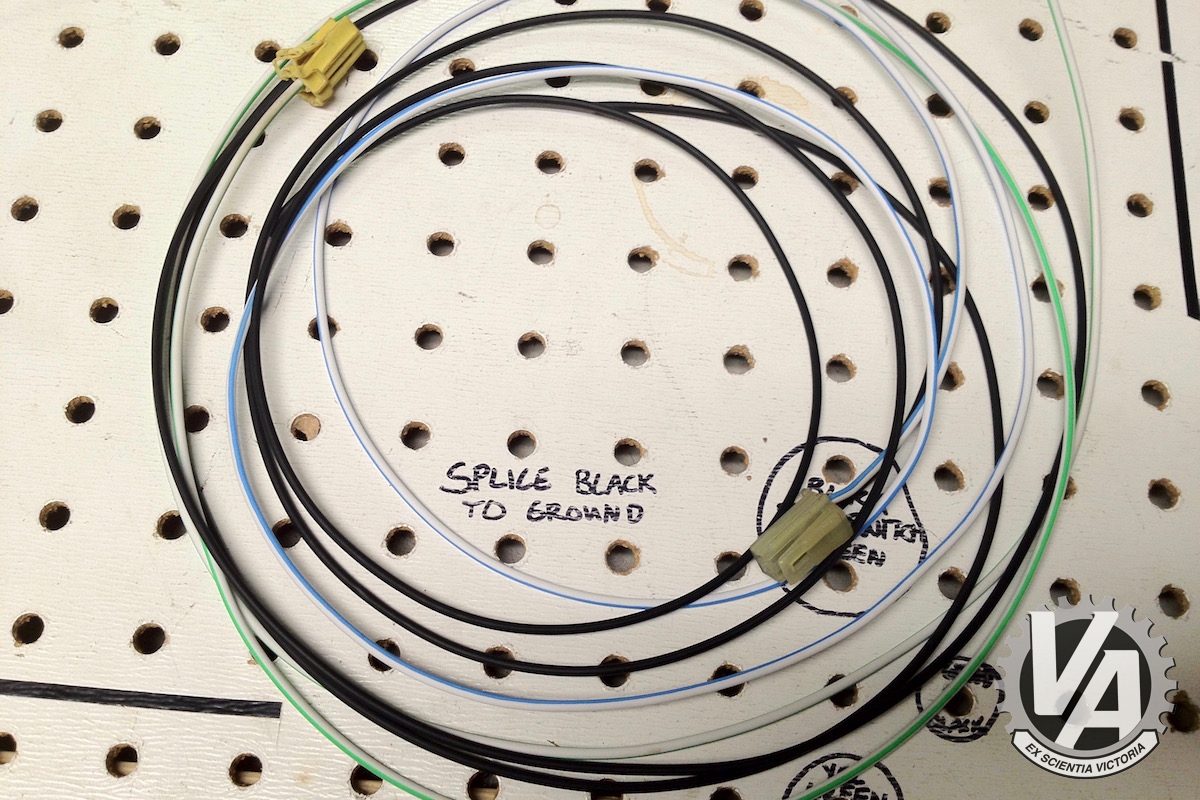
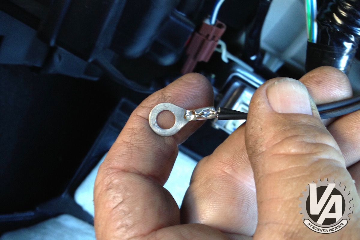
Each of these connectors gets two wires connected to it. One wire from each is going to be a ground, so crimp an 1/4 eyelet on. Once they’re plugged in, find one of the many 6mm bolts or studs under the dash and bolt the eyelet down to ground it. The other wire from each connector will be extended over the passenger side of the car and spliced to wires we will remove from the C101 connector by the ECU.
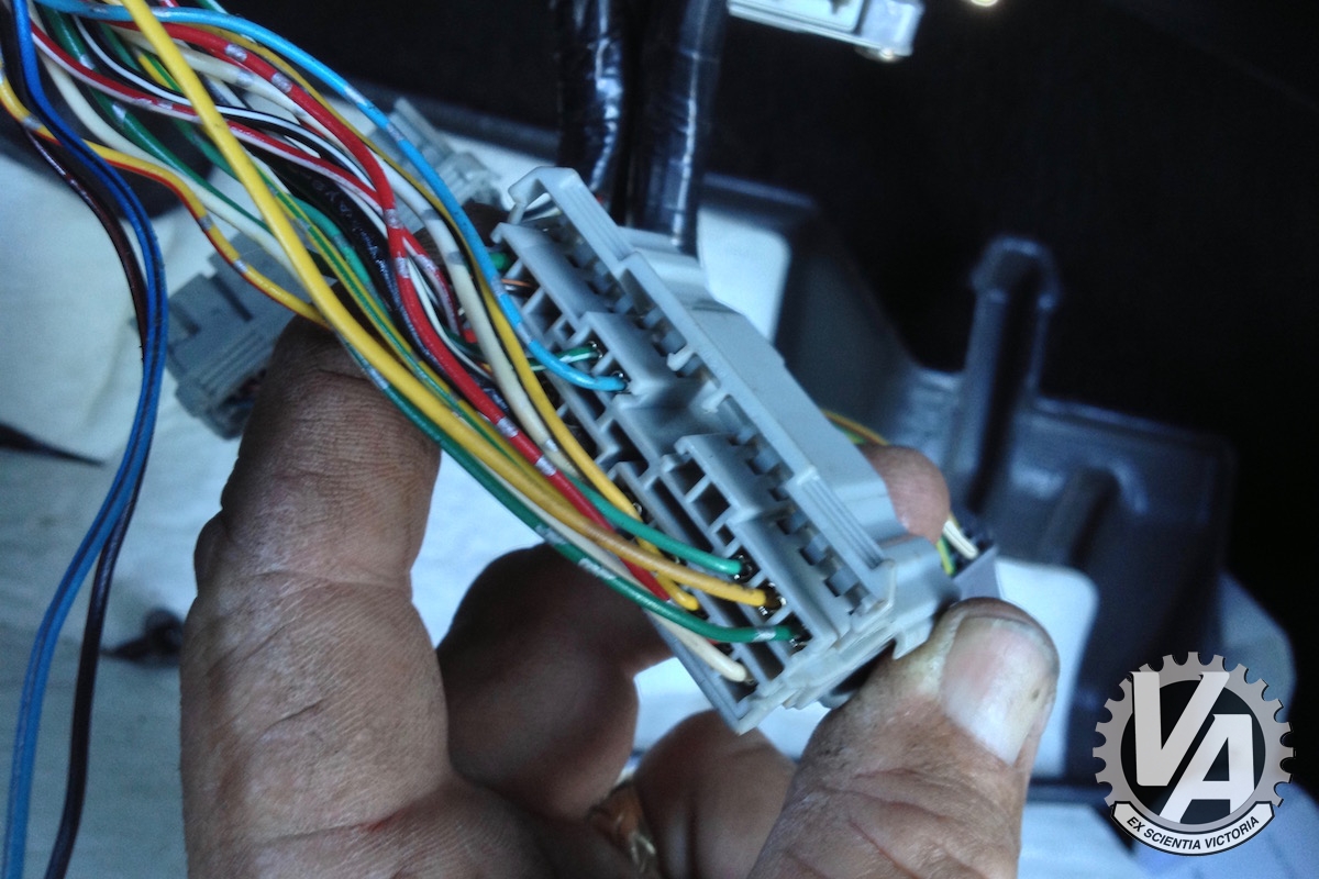
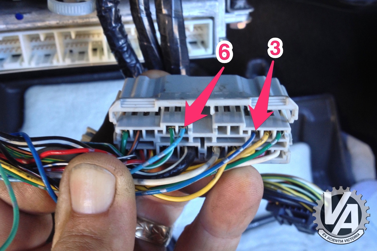
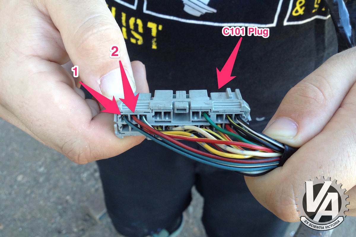
The next mods will be with the C101 connector. Remember it’s the big grey one near the ECU that has 20 openings for pins. We want the car harness side, not the engine harness side.
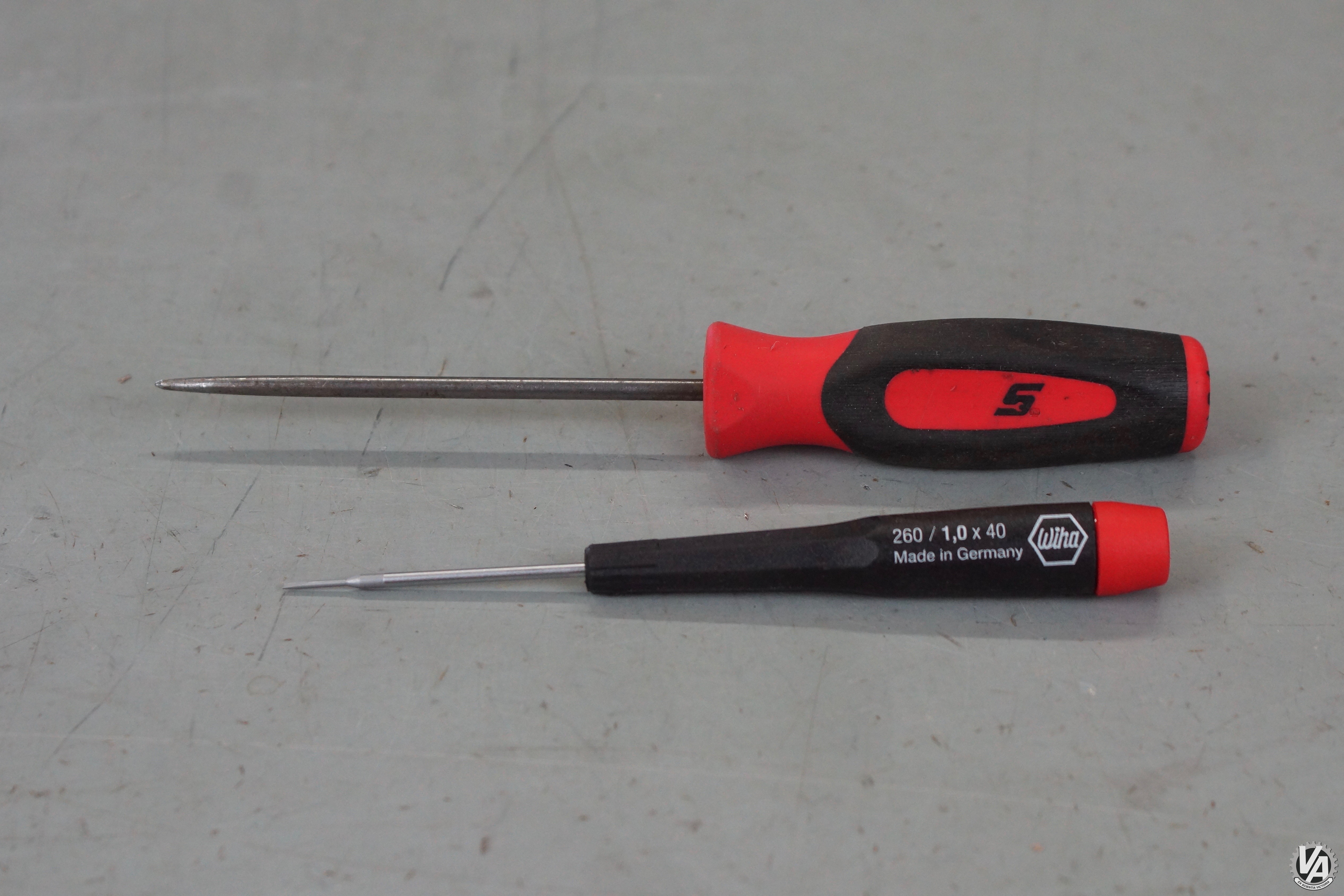
We’re going to make several changes to this connector so you need to know how to take out the individual pins. The connector pins are extracted using techniques explained in this earlier vtec.academy article. Read the part about the OBD1 ECU pins. The OBD1 ECU connectors look a little different, but the procedure is identical. You’ll need a pick tool and a 1mm jeweler’s screwdriver. This is the one I like, it’s made by Wiha and is high quality tool steel. It’s small and durable.
Remove the light blue wire from pin 6 on C101. Solder it to the wire coming from the clutch position switch. Clip the blue with white stripe wire from pin 3 on C101. Leave at least an inch of wire hanging out of the C101 connector so we can connect to that pin later. Solder the blue/white wire you just cut off to the wire coming from the clutch interlock switch.
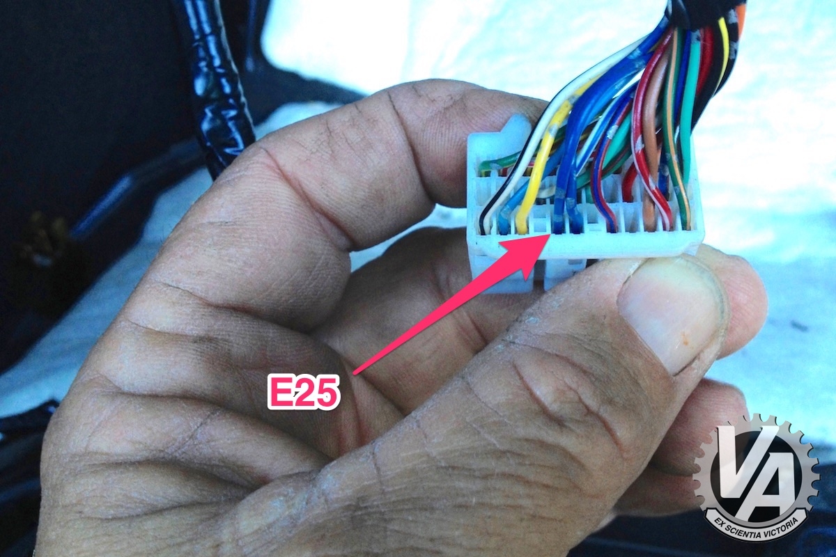
On 2001-2004 manual transmission cars, the VSS signal for the dash also comes through the C101 plug. In the automatic cars, and 2005-2006 manual cars, the speed signal comes from the ECU E plug. Since our car is a a 2004 RSX we need to get the signal to the C101 plug. There is a blue wire with white stripe located in the 25th position of the E plug. Cut that wire and solder it to the short piece of wire you left at C101 pin 3.
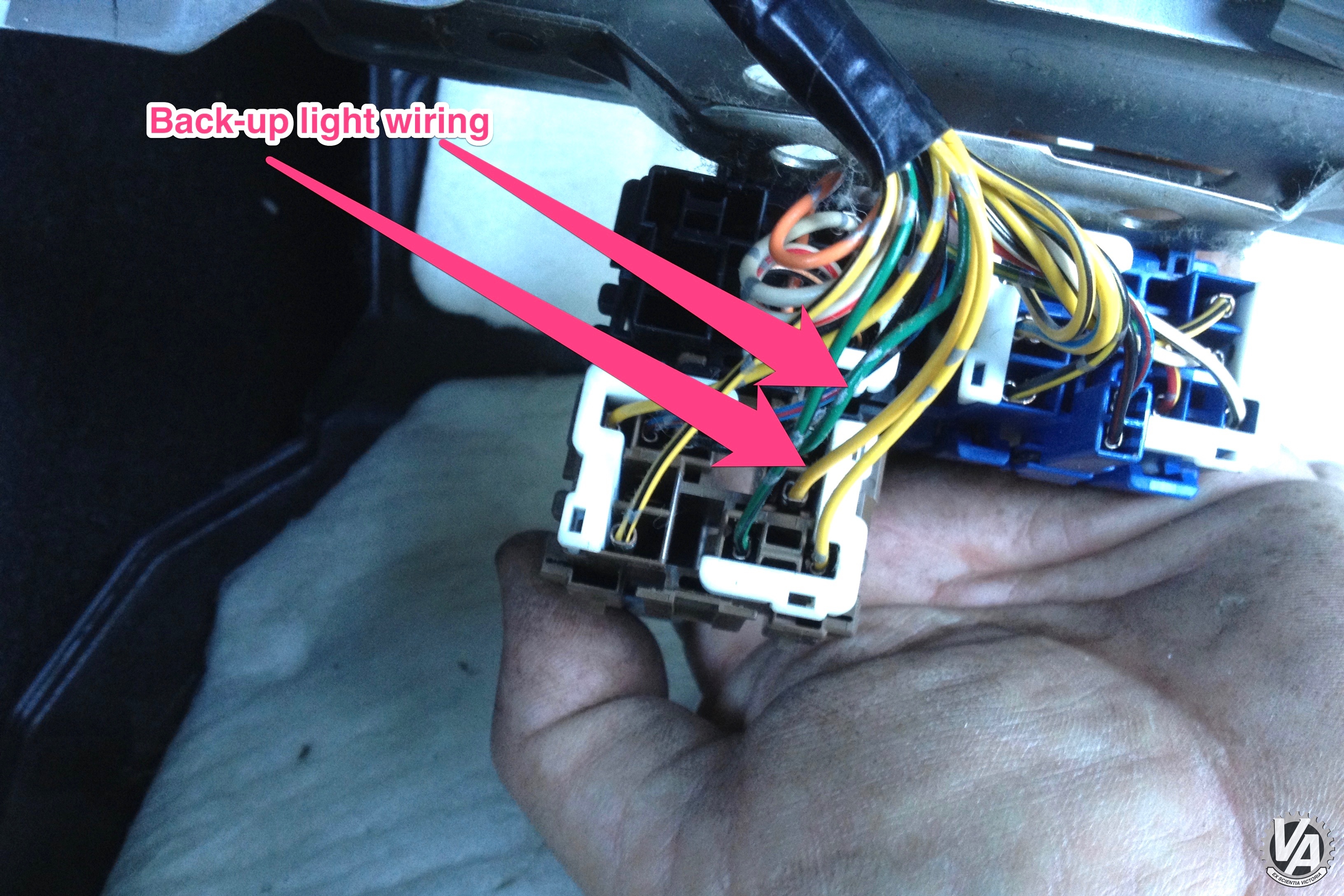
The backup light wiring for the manual transmission also comes through the C101 plug. With the automatic, the transmission range switch grounded a relay to switch on the back-up lights. Now that we have a manual trans, there is no relay, but the reverse switch on the transmission makes the connection to switch on the lights. So we need to remove the relay and move those wires to the C101 plug.
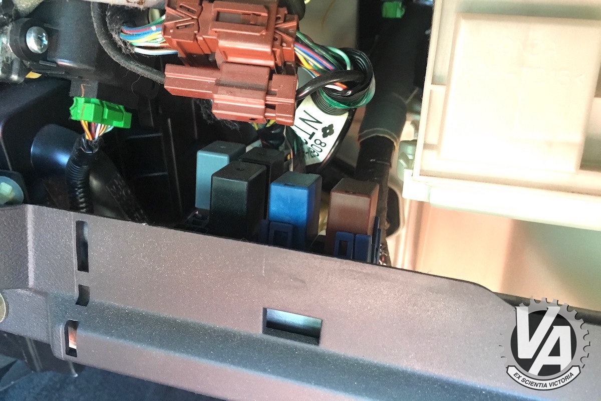
The reverse relay is in this group of relays behind the glove box. The back up light relay has two yellow wires, a green wire and green with a black stripe wire running to it. Clip one of the yellow wires and the green wire from the relay connector.
The wiring conversion for the chassis is complete. Next up we need to figure out the engine harness and install the new transmission.

No Comments